
PI312 REV B
Interactive Assembly, Calibration Guide & Bill of Materials for the 500 / 51X Series Preamp Kit
Manual Contents
2. Line Level Conversion (PAD Mod Option)
3. Step-by-Step Assembly Guide
3.1 Mainboard Resistors and Diodes
3.2 IC Sockets, Transistors, Small Capacitors & LED Meter
3.3 Potentiometers, Switches & Transformer
3.5 Front Panel Fitment & LED Soldering
4. Final Assembly and Voltage Check
4.1 Pre-Flight Power On and Voltage Check
1. Introduction
Welcome to the build manual for the PI312 Rev B Preamp Module.
The PI312 Rev B is a classic American-style console preamplifier engineered for the 500 / 51X series rack format (+16V / -16V rails). Inspired by the legendary 312-series circuitry, this module pairs a high-performance transformer-balanced input stage with a custom transformer-coupled output stage, delivering the punchy, authoritative sound characteristic of vintage American consoles.
In this Rev B revision, the module features an upgraded 4-layer PCB design for superior shielding, significantly reduced noise floor, integrated variable High Pass (Low Cut) and Low Pass (High Cut) filters, as well as full compatibility with the DIYRE Colour Module ecosystem for custom analog saturation and character.
Key Features of the PI312 Rev B:
-
Classic American Topology: Based on the iconic 312-series circuit, utilizing discrete op-amps (DOA).
-
Transformer Output: High-quality transformer output stage with selectable ratio (1:2 to 1:3) via internal jumper.
-
Integrated Variable Filters: Sweepable Low Cut / HPF (10 Hz to 250 Hz) and High Cut / LPF (3.5 kHz to 20 kHz) filter sections with dedicated enable switches.
-
DIYRE Colour Module Slot: Integrated socket and drive control for inserting custom analog saturation modules.
-
4-Layer Low-Noise PCB: Rev B layout optimization with ground planes for ultra-low noise floor and shielding.
-
Flexible Peak & Metering Display: Dedicated Peak LED (set to +18 dBu post-preamp) and multi-segment LED ladder with jumper selection for PRE- or POST-FADER metering.
-
Utility Features: Selectable +48V Phantom Power, Phase Invert (POL), and 20 dB Attenuation Pad (with optional Line-Level Mod).
This manual will guide you step-by-step through component selection, board assembly, initial voltage checks, and precision alignment. Please take your time, read all instructions carefully before soldering, and double-check component polarities at each stage.

2. Line Level Conversion (PAD Mod Option)
The resistors included in the kit configure the 20 dB PAD switch according to the original schematic. To convert the PAD switch into a Line-to-Mic Level Switch (optimizing for line-level interface signals at 42 dB gain for unity throughput), use these values:
Line Mod Resistor Values:
-
R_301: 5.1 kOhm (5k1)
-
R_302: 5.1 kOhm (5k1)
-
R_303: 82 Ohm (82R)
3. Step-by-Step Assembly Guide
3.1 Mainboard Resistors and Diodes
-
DOA Sockets: Place the Discrete Op-Amp (DOA) sockets from the back of the PCB and solder them securely with sufficient solder.
-
Resistor Modifications:
-
Locate RM126 and change to 2k.
-
Locate RM127 and change to 1k.
-
-
Place and solder all other resistors and signal diodes. Important: Double-check diode polarity (cathode stripe matches PCB silkscreen) before soldering.
-
Colour Module LED Configuration (Choose one option before soldering):
-
Option A: Using an RGB LED for Colour Indication
-
Add a small solder bridge on the back of the PCB near the Colour Module connector.
-
Do NOT install the 6K81 resistor at position R_C_RGB1 (leave open).
-
-
Option B: Using a Yellow LED for Colour Indication
-
Do NOT bridge the solder pads on the back.
-
Install the supplied 6K81 resistor at position R_C_RGB1.
-
-


3.2 IC Sockets, Capacitors & LED Meter Board
-
Install IC sockets on the mainboard (ensure notch orientation matches PCB silkscreen).
-
Solder film capacitors (WIMA) and electrolytic capacitors on the mainboard and LED Meter subboard.
-
Trim all component leads on the underside as short as humanly possible to avoid shorting against adjacent 500-series modules.
-
Bend and install the LM317 voltage regulator as shown in reference photos. Ensure its metal tab does not touch adjacent resistors.
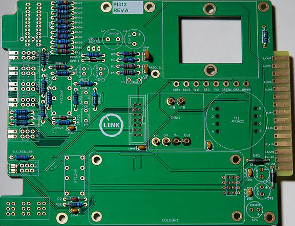


3.3 Potentiometers, Switches & Transformer
-
Potentiometers Allocation:
-
C50K: Low Cut (HPF) Frequency
-
B10K: High Cut (LPF) Frequency
-
B20K: Colour Module Drive
-
6-Gang T-Pad: Output Fader
-
-
Solder only one pin per potentiometer first to allow for mechanical alignment. Do not solder remaining pins yet.
-
Install the Grayhill Gain Switch, place the stop pin at the 12 o'clock position, and secure it with the provided sticker so it cannot move.
-
Transformer Assembly:
-
Output Transformer: Secure with long screws, washers, and nuts on the bottom. Wire the leads carefully; use heatshrink on all four connections. Pass leads through PCB holes and solder from the bottom. Trim leads and shrink heatshrink.
-
Input Transformer: Place with a small gap between the PCB and transformer body (solder one pin first, check alignment, then solder remaining pins).
-


3.4 Board Cleaning
-
Clean the mainboard and LED meter subboard thoroughly using Isopropyl Alcohol or flux remover to clear away all solder residue. Allow to dry completely.
-
Warning: Do NOT clean the PCB with liquids AFTER trimpots, potentiometers, Grayhill switches, or pushbuttons are installed. Solvents will wash away internal conductive grease and ruin electrical contact permanently.
3.5 Front Panel Fitment & LED Soldering
LED Leg Trimming Reference:
-
Mainboard LEDs: Trim long leg (Anode, +) to 8 – 10 mm.
-
1x Red, 2x Green, 2x Yellow, 1x RGB (or Yellow for Colour slot).
-
-
LED Meter Board LEDs: Trim long leg (Anode, +) to 12 – 14 mm.
-
2x Red, 6x Green, 4x Yellow.
-
-
Tip: Keep the ground leg slightly longer on RGB LEDs to easily identify it during placement.
Front Panel Assembly Steps:
-
Attach the front panel temporarily to the mainboard using spacers and hardware.
-
Insert pushbuttons and align switch bodies so they sit perfectly centered in the front panel cutouts. Solder switch pins completely, then trim leads short.
-
Apply paper masking tape over the front panel LED cutouts to establish a flat height stop.
-
Mainboard LEDs: Insert LEDs into position flush against the tape.
-
Yellow/RGB Colour LED: If using a Yellow LED, solder the long leg to R/Y and the short leg to the unlabeled pad. If using RGB, follow the dedicated pinout guide.
-
Solder one leg first, verify depth/alignment, then solder remaining legs.
-
-
Disassemble the front panel. Mount the LED Meter Board onto the mainboard using 25 mm spacers and screws. Re-attach the front panel and tighten bracket nuts.
-
Final Potentiometer Alignment: With the front panel locked in place, solder all remaining pins of the LED Meter board potentiometers (they are now perfectly centered).
-
Meter LEDs Placement: The LED Meter board pads feature long dashes (+) for long legs and short dashes (-) for short legs. Insert LEDs step-by-step from the front, solder them temporarily from the top side, then remove the front panel to complete soldering from the back side.


4. Final Assembly and Voltage Check
4.1 Pre-Flight Power On and Voltage Check
-
Ensure NO ICs/DOAs are inserted into any sockets.
-
Power the unit via your 500-series rack test rig using ribbon cables.
-
Verify relay switching operation and switch LED activity.
-
Set multimeter to DC Volts and measure supply voltages at IC sockets (relative to ground):
-
Verify DOA socket voltages according to silk-screened labels.
LM339 - Pin 3 (+15.3V) - Pin 12 (-15.3V)
TL074 - Pin 4 (+15.3V) - Pin 11 (-15.3V)
NE5532A - Pin 8 (+15.3V) - Pin 4 (-15.3V)
4.2 IC Installation and Hardware Assembly
-
Populate all IC sockets (LM339, TL074, NE5532A). Pay strict attention to Pin 1 notch orientation and verify each IC is in its designated position.
-
Re-attach the front panel using 3 mm hardware, spacers, and potentiometer nuts.
-
Knob Cap Color Setup:
-
15 mm Yellow Cap: Gain Control
-
15 mm Blue Cap (6mm Shaft): Output Fader Control
-
11 mm Blue Caps: Low Cut (HPF) and High Cut (LPF) Controls
-
11 mm Red Cap: Colour Module Drive Control
-


5. Calibration Guide
Calibration requires passing pure sine waves through the module while measuring AC voltages at test points or monitoring DAW input levels (e.g., via REW - Room EQ Wizard).
Test Requirements:
-
Headroom: Maintain at least 10 dB headroom on your audio interface converter to prevent clipping during testing.
-
Reference Levels:
-
0 dBu Reference: 0.775 V RMS (AC)
-
+6 dBu Reference: 1.545 V RMS (AC)
-
Preamp Calibration Input Signal: -40 dBu (0.007 V RMS / 7 mV AC) between Pins 2 & 3 of XLR input.
Recommended Resources:
Initial Check:
-
Set initial controls:
-
All Pushbuttons: OFF (Disengaged)
-
Mic Gain: Lowest setting
-
Output Fader: 0 dB position
-
-
Inject a White Noise signal at -40 dBu into the microphone input.
-
Increase Mic Gain to a comfortable monitoring level.
-
Verify filter operations (sweep Low Cut and High Cut), PAD engagement, POL phase inversion, and Colour Module drive.
-
Verify +48V Phantom Power voltage using a phantom-powered microphone or active DI box.
-
Once functional verification is complete, proceed to precision calibration using a 1 kHz Sine Wave at -40 dBu.
LED Meter Calibration (R_meter1)
-
Set controls: All switches OFF, Gain at lowest setting, Output Fader at 0 dB.
-
Inject a 1 kHz Sine Wave at -40 dBu (0.007 V AC) into the XLR input.
-
Adjust Gain until your multimeter measures exactly 1.554 V AC between PREOUT1 and GND.
-
Adjust trimpot R_meter1 until all Green LEDs on the meter ladder just illuminate.
Low Cut (HPF) Filter Calibration (R_LC_TRIM)
-
Maintain setup (1.554 V AC measured at PREOUT1).
-
Note the baseline level in your measuring system.
-
Engage the Low Cut (HPF) switch on the front panel.
-
Adjust trimpot R_LC_TRIM until your measuring system input level matches the baseline reading (unity pass-through at 1 kHz).
High Cut (LPF) Filter Calibration (R_HC_TRIM)
-
Maintain setup (1.554 V AC measured at PREOUT1).
-
Disengage Low Cut and engage the High Cut (LPF) switch on the front panel.
-
Note the baseline level in your measuring system.
-
Adjust trimpot R_HC_TRIM until your measuring system input level matches the baseline reading (unity pass-through at 1 kHz).