
SLQ51X BLACK REV C
Manual Contents
3.2 IC Sockets and Ceramic Caps
3.3 Film Capacitors and Inter-Board Connectors
3.4 Relays, Voltage Regulators, JFETs and Electrolytics
3.5 Board Cleaning and Trimpots
3.6 Potentiometers, Switches and Subboard Assembly
3.7 Front Panel Fitment and LED Alignment
4. Final Assembly and Voltage Check
4.2 Pre Flight Power On and Voltage Check without ICs
1. Introduction
Welcome to the build manual for the SLQ51X Equalizer Kit.
The SLQ51X is a high-performance 4-band parametric equalizer module engineered for the popular 500 / 51X series rack format. Inspired by classic analog console EQ designs, it combines broad tone-shaping flexibility with high-grade components to deliver precise sound control for both tracking and mixing.
Key Features of the SLQ51X:
-
4 Bands of Equalization (LF, LMF, HMF, HF) with sweepable frequencies and switchable Bell/Shelf modes.
-
Precision Variable Q control on mid-bands for pinpoint notch filtering or wide tonal shaping.
-
Integrated High Cut (8 kHz) and Low Cut (80 Hz) filter section with configurable cutoff frequencies.
-
High-grade THAT-series balanced line receivers and drivers for maximum headroom and low noise floor.
-
True-bypass relay switching for silent circuit engagement.
This manual will guide you step-by-step through component selection, board assembly, initial voltage checks, and precision alignment. Please take your time, read all instructions carefully before soldering, and double-check component polarities at each stage.

2. Filter Configurations & Resistor Values
The High and Low Cut filters are set to fixed frequencies. By default, the kit is supplied with standard values for 80 Hz (Low Cut) and 8 kHz (High Cut).
If you wish to customize these cutoff frequencies for your application, you can easily change the filter response by swapping three identical resistors per filter section before assembly.
Tip: To learn more about passive and active RC filter calculations, we recommend the online calculator at sim.okawa-denshi.jp/en/Fkeisan.htm.
Low Cut Resistor Values
(Change RH3, RH4, and RH5 to the exact same value)
Cutoff Frequency: 50 Hz - Resistor Value: 33 kOhm
Cutoff Frequency: 60 Hz - Resistor Value: 27 kOhm
Cutoff Frequency: 80 Hz - Resistor Value: 20 kOhm (Standard supplied with kit)
Cutoff Frequency: 100 Hz - Resistor Value: 16 kOhm
Cutoff Frequency: 120 Hz - Resistor Value: 13 kOhm
Cutoff Frequency: 160 Hz - Resistor Value: 9.1 kOhm
High Cut Resistor Values
(Change RL3, RL4, and RL5 to the exact same value)
Cutoff Frequency: 5 kHz - Resistor Value: 330 Ohm
Cutoff Frequency: 6 kHz - Resistor Value: 270 Ohm
Cutoff Frequency: 8 kHz - Resistor Value: 200 Ohm (Standard supplied with kit)
Cutoff Frequency: 10 kHz - Resistor Value: 160 Ohm
Cutoff Frequency: 12 kHz - Resistor Value: 130 Ohm
Cutoff Frequency: 16 kHz - Resistor Value: 91 Ohm
Note: The calibration procedure for custom filter frequencies is identical to the standard calibration shown at the end of this guide.
3. Step-by-Step Assembly Guide
3.1 Resistors and Diodes
-
Place and solder all low profile resistors on the PCB according to the Bill of Materials. If customizing cutoff frequencies, insert your alternative resistor values for RH3 through RH5 or RL3 through RL5 now.
-
Install all diodes.
-
Important: Double check the orientation and polarity cathode stripe matching PCB silkscreen of all diodes before soldering.

3.2 IC Sockets and Ceramic Capacitors
-
Install all IC sockets (ensure notch orientation matches the PCB silkscreen).
-
Solder the low-profile ceramic capacitors:
-
37x 100nF
-
12x 22pF
-
4x10pF
-

3.3 Film Capacitors and Inter-Board Connectors
-
Place and solder all WIMA film capacitors.
-
Install the PCB board connectors as shown in the reference photos:
-
On the small subboard, ensure the short pins are seated flush against the PCB before soldering.
-
Crucial: Press the headers firmly onto the board during soldering to guarantee they sit perfectly straight and level. This is vital for flawless mechanical alignment during final assembly.
-

3.4 Relays, Voltage Regulators, JFETs and Electrolytics
-
Solder the signal relays, voltage regulator, and JFET transistors.
-
Install the electrolytic capacitors:
-
Attention: CP1 and CP2 are polarized. Verify correct alignment plus or minus before soldering.
-
All other electrolytic capacitors in this kit are bipolar or non polarized, so orientation does not matter for those.
-

3.5 Board Cleaning and Trimpots
-
Clean the PCB thoroughly using Isopropyl Alcohol or flux remover to clear away all solder residue.
-
Allow to dry, then install and solder all trimpots.
-
Warning: Do NOT clean the PCB with liquids AFTER installing trimpots, potentiometers, or switches. Solvents can penetrate component casings, wash away internal conductive grease, and ruin electrical contact permanently.
3.6 Potentiometers Switches and Subboard Assembly
Potentiometer Taper Guide
Before soldering, check the code printed on the potentiometer body (Letter = Taper / Number = Value):
-
A – Logarithmic / Audio (e.g., A10K): Non-linear curve matching human hearing. Used for Q-factor and frequency controls where fine control at lower settings is needed.
-
B – Linear with Center Detent (e.g., B50K): Even resistance change across full turn, featuring a tactile notch at 12 o'clock. Used for Gain boost/cut controls to feel the 0 dB center position.
-
C – Reverse Logarithmic / Anti-Log (e.g., C50K): Inverse curve designed for frequency sweeps, giving a smooth and natural sweep feel across high-frequency ranges.
Lower Subboard:
-
Trim all pins of previously soldered pin rows on the bottom of the lower subboard as short and flush as possible to prevent shorts in your rack.
-
Insert all potentiometers into the subboard simultaneously.
-
Solder only one middle pin per potentiometer first.
-
Press each potentiometer flat against the board and verify its body is perfectly aligned with the printed silkscreen outlines. Verify Gain pots with center detents and Q pots are in their designated spots.
-
Attach the mounting bracket to the pots, tighten the nuts, and solder all remaining pins.
-
Trim all potentiometer pins short, then temporarily remove the mounting bracket.
Upper Subboard:
-
Trim all pre soldered leads on the underside as short as possible.
-
Insert all potentiometers and switches. Secure each part with a single solder joint first.
-
Check visual alignment against the silkscreen, install the blank bracket, and solder all remaining pins. Trim all leads short.


3.7 Front Panel Fitment and LED Alignment
-
Attach the front panel to the subboard assembly using the provided spacers and hardware or clamps to align pushbuttons and switches within their panel cutouts.
-
Solder all switch pins completely, then trim their leads short.
-
Prepare LEDs: Trim LED leads at slightly different lengths so you can easily distinguish the anode longer leg from the cathode shorter leg.
-
Solder LEDs: Insert LEDs into position so they sit flush with the front panel surface. Solder one leg first to adjust depth and height, verify fitment, then solder the second leg.
-
Disassemble the front panel and mounting bracket once alignment is complete to prepare for joining the boards.


4. Final Assembly and Voltage Check
4.1 Board Joining
-
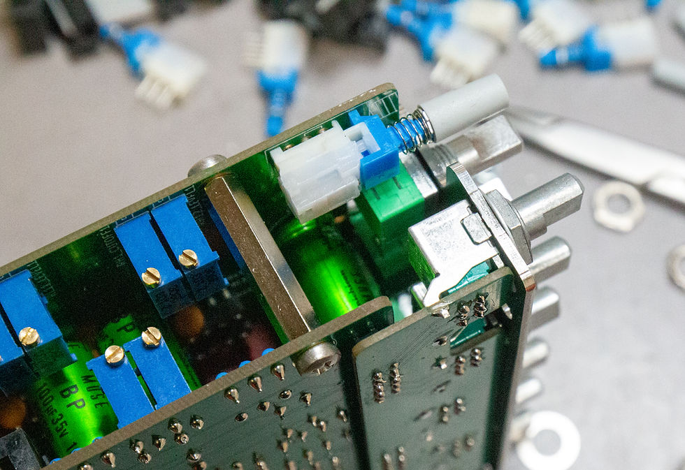
Connect the mainboard and lower subboard using two M3 screws and nuts as temporary height spacers in the corners.
-
Solder one pin per header row first, press the boards tightly together, then solder all remaining header pins and trim flush.
-
Remove the temporary corner spacer screws.


4.2 Pre Flight Power On and Voltage Check without ICs
-
Ensure NO ICs are inserted into any sockets.
-
Connect the joined boards using the ribbon cables and power the unit via your 500 series rack or lunchbox.
-
Set your multimeter to DC Volts and measure supply voltages at the socket pins relative to chassis ground:
-
NE5534A socket: Pin 7 equals +15.3 Volts DC, Pin 4 equals -15.3 Volts DC
-
THAT 1246 socket: Pin 7 equals +15.3 Volts DC, Pin 4 equals -15.3 Volts DC
-
THAT 1646 socket: Pin 6 equals +15.3 Volts DC, Pin 5 equals -15.3 Volts DC
-
-
Verify that status LEDs light up and relays respond to switching commands properly.
-
Power off the rack.
4.3 IC Installation and Hardware Assembly
Once correct power rails of approximately plus minus 15 point 3 Volts are confirmed, insert all ICs into their sockets. Pay strict attention to the Pin 1 notch orientation on every IC package.
-
Re attach mechanical hardware: brackets, ribbon cables, subboards, 25 millimeter inter board spacers, and the front panel using the M7 and M9 potentiometer nuts as well as M3 front hardware.
-
Fit the color coded knob caps to their respective frequency bands:
-
Red for HF Band
-
Green for HMF Band
-
Blue for LMF Band
-
Black for LF Band
-


5. Calibration Guide
Calibration is straightforward and requires playing sine waves into the unit while measuring the output level.
Test Requirements:
-
Headroom: Keep at least 20 dB of headroom on your audio interface to avoid clipping during boost adjustments.
-
Software: Any DAW with an oscillator and level meter works, but REW (Room EQ Wizard) is highly recommended.
-
Reference Level: Max level reference: +6 dBu (1.545 V RMS). Test signal level: -12 dBu (0.195 V RMS).
Recommended Resources:
Initial Check:
-
Set all front panel gain and frequency controls to their center/detent positions.
-
Engage the EQ in circuit.
-
Send a White Noise signal through the unit and verify using an oscilloscope, analyzer, or monitoring system that all bands boost, cut, and sweep correctly.
-
Switch generator output to a Sine Wave to begin precision calibration.
HMF Band Calibration:
-
Set all controls to center detent.
-
Set sine oscillator to 3 kHz.
-
Engage EQ.
-
Set HMF Boost to maximum and Q to narrowest setting.
-
Sweep the HMF Frequency control slightly until you find the exact peak in output level.
-
Adjust the QADJ HMF trimpot on the board until the peak output reads exactly +18 dB of boost relative to bypassed level.
LMF Band Calibration:
-
Set all controls to center detent.
-
Set sine oscillator to 1 kHz.
-
Engage EQ.
-
Set LMF Boost to maximum and Q to narrowest setting.
-
Sweep the LMF Frequency control to find the peak output level.
-
Adjust the QADJ LMF trimpot until the peak output reads exactly +18 dB of boost.
LF Band Calibration:
-
Set all controls to center detent.
-
Set sine oscillator to 200 Hz (Bell Mode / Standard).
-
Engage EQ.
-
Set LF Boost to maximum.
-
Sweep LF Frequency to locate maximum output peak.
-
Adjust the QADJ LF trimpot until the peak output reads exactly +18 dB of boost.
HF Band Calibration:
-
Set all controls to center detent.
-
Set sine oscillator to 8 kHz (Bell Mode / Standard).
-
Engage EQ.
-
Set HF Boost to maximum.
-
Sweep HF Frequency to locate maximum output peak.
-
Adjust the QADJ HF trimpot until the peak output reads exactly +18 dB of boost.
Low Cut (LC) Filter Calibration:
-
Set all controls to center detent.
-
Set sine oscillator to 1 kHz.
-
Engage Low Cut and measure the level. Adjust the LC LEVEL trimpot so the level matches the bypassed/disengaged state.
-
Change oscillator to 80 Hz.
-
Adjust the LC CUTOFF trimpot until you observe a -3 dB drop at 80 Hz.
-
Switch oscillator back to 1 kHz and fine-tune LC LEVEL if needed.
-
Repeat steps 4 to 6 until both unity gain at 1 kHz and a -3 dB drop at 80 Hz are achieved.
High Cut (HC) Filter Calibration:
-
Set all controls to center detent.
-
Set sine oscillator to 1 kHz.
-
Engage High Cut and adjust the HC LEVEL trimpot to match bypassed level (unity gain).
-
Change oscillator to 8 kHz.
-
Adjust the HC CUTOFF trimpot until you observe a -3 dB drop at 8 kHz.
-
Switch back to 1 kHz to re-check unity gain, then verify -3 dB drop at 8 kHz again.
-
Repeat until both unity gain at 1 kHz and -3 dB cutoff at 8 kHz are calibrated.